Mastering Terminal Strip Editing in Autodesk Electrical: A Comprehensive Guide
The Terminal Strip Editor in Autodesk Electrical is a powerful tool designed to streamline the management and configuration of terminal strips within electrical schematic diagrams. It enables designers and engineers to define, customize, and manipulate terminal strip layouts, facilitating efficient wiring design, documentation, and manufacturing processes. In this comprehensive guide, we will explore the intricacies of using the Terminal Strip Editor in Autodesk Electrical, providing detailed instructions, best practices, and expert tips to help you master this essential aspect of electrical design.
Understanding the Significance of the Terminal Strip Editor
The Terminal Strip Editor plays a pivotal role in electrical design, offering several key benefits:
- Customization: Designers can customize terminal strip layouts, configurations, and properties to meet specific project requirements and standards.
- Efficiency: The Terminal Strip Editor streamlines the wiring design process by providing intuitive controls and automation features for terminal placement and connection.
- Documentation: Terminal strip configurations defined in the editor are reflected in schematic diagrams, bill of materials (BOM), and manufacturing documentation, ensuring consistency and accuracy across design documents.
Using the Terminal Strip Editor in Autodesk Electrical
Now, let’s delve into the step-by-step process of using the Terminal Strip Editor within Autodesk Electrical:
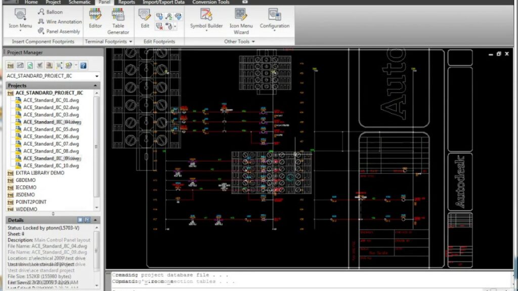
Step 1: Accessing the Terminal Strip Editor
- Menu Navigation: Navigate to the “Terminal Strip Editor” menu or toolbar within Autodesk Electrical to access the Terminal Strip Editor.
- Workspace Configuration: Set up the workspace to display the Terminal Strip Editor interface, which typically includes options for terminal strip layout and configuration.
Step 2: Defining Terminal Strip Properties
- Terminal Strip Selection: Select the terminal strip within the schematic diagram that you wish to edit or configure.
- Properties Panel: Access the properties panel to define terminal strip properties such as strip type, manufacturer, part number, and description.
Step 3: Configuring Terminal Placement
- Terminal Layout: Define the layout and arrangement of terminals within the terminal strip, including the number of terminals per row, spacing, and orientation.
- Automatic Placement: Utilize automatic placement tools to place terminals on the strip based on predefined settings and spacing requirements.
Step 4: Wiring Connection Management
- Wire Connections: Manage wiring connections to terminals within the terminal strip, ensuring proper routing and connectivity between components.
- Wire Routing: Define wire routing paths and routes within the terminal strip to optimize wiring layout and organization.
Step 5: Validating and Verifying Connections
- Connection Verification: Validate and verify wiring connections within the terminal strip to ensure accuracy and compliance with design specifications.
- Cross-Referencing: Utilize cross-referencing tools to verify connections between terminals and associated components within the schematic diagram.
Step 6: Saving and Updating Terminal Strip Configurations
- Save Changes: Save the updated terminal strip configuration within Autodesk Electrical to apply the changes to the schematic diagram and associated design documents.
- Revision Control: Implement a revision control system to track changes, revisions, and updates to terminal strip configurations over time.
Best Practices for Terminal Strip Editing
To optimize the use of the Terminal Strip Editor in Autodesk Electrical, consider the following best practices:
Planning and Preparation
- Pre-Design Review: Review project requirements, specifications, and standards before configuring terminal strip layouts to ensure alignment with project needs.
- Component Compatibility: Verify compatibility between terminal strip configurations and associated components, connectors, and wiring harnesses.
Organization and Efficiency
- Standardization: Establish standardized templates and configurations for terminal strips to promote consistency and efficiency across design projects.
- Labeling and Annotation: Utilize labeling and annotation tools within Autodesk Electrical to provide additional context and information for terminal strip configurations.
Collaboration and Communication
- Team Collaboration: Collaborate with design team members, engineers, and stakeholders to gather input, feedback, and insights during the terminal strip design process.
- Documentation Sharing: Share terminal strip configurations and documentation with manufacturing teams, assembly technicians, and contractors to ensure alignment and accuracy during production and installation.
Conclusion
The Terminal Strip Editor in Autodesk Electrical empowers designers and engineers to efficiently configure and manage terminal strip layouts within electrical schematic diagrams. By following the steps outlined in this guide and adhering to best practices, you can master the use of the Terminal Strip Editor, streamline wiring design workflows, and ensure consistency and accuracy in terminal strip configurations. Whether you’re designing control panels, machinery, or industrial automation systems, proficiency in terminal strip editing will enable you to deliver superior results, optimize productivity, and exceed client expectations.