Mastering Stress Analysis in SolidWorks Simulation: A Comprehensive Guide
Introduction: SolidWorks Simulation is a powerful tool integrated within the SolidWorks CAD software suite, enabling engineers and designers to perform advanced stress analysis, structural simulation, and validation of mechanical components and assemblies. With its intuitive interface and robust capabilities, SolidWorks Simulation allows engineers to predict and analyze the behavior of designs under various loading conditions, helping to ensure structural integrity, optimize performance, and accelerate the product development process. In this comprehensive guide, we’ll explore the intricacies of performing stress analysis in SolidWorks Simulation, covering everything from model preparation to result interpretation and optimization.
Section 1: Introduction to SolidWorks Simulation 1.1 Overview of SolidWorks Simulation: SolidWorks Simulation is a finite element analysis (FEA) software tool that allows engineers to simulate and analyze the behavior of mechanical components and assemblies under real-world loading conditions. It offers a range of simulation capabilities, including linear and nonlinear static analysis, dynamic analysis, thermal analysis, and fatigue analysis. SolidWorks Simulation is fully integrated with the SolidWorks CAD environment, allowing engineers to seamlessly transition from design to simulation without the need for data translation or model reconstruction.
1.2 Key Features of SolidWorks Simulation: SolidWorks Simulation offers a range of features designed to streamline the stress analysis workflow. These include a user-friendly interface for model setup and simulation, a comprehensive library of material properties and loads, advanced meshing tools for discretizing the geometry, and robust solvers for solving complex simulation problems. SolidWorks Simulation’s tight integration with SolidWorks CAD enables engineers to make design changes directly within the simulation environment, facilitating iterative design optimization and validation.
Section 2: Setting Up Stress Analysis Models in SolidWorks Simulation 2.1 Model Preparation: The first step in performing stress analysis in SolidWorks Simulation is to prepare the CAD model of the component or assembly to be analyzed. Engineers must ensure that the geometry is properly modeled, with appropriate features, dimensions, and constraints. SolidWorks Simulation supports a wide range of CAD file formats, allowing engineers to import models from various CAD software packages or create them directly within SolidWorks.
2.2 Applying Boundary Conditions and Loads: Once the CAD model is prepared, engineers must define the boundary conditions and loads that represent the operating conditions of the component or assembly. This includes specifying fixed constraints to represent fixed supports or constraints, applying loads such as forces, pressures, or torques to represent external loads, and defining contact conditions between interacting components. SolidWorks Simulation provides intuitive tools for defining boundary conditions and loads directly within the CAD environment.
Section 3: Meshing and Analysis Setup 3.1 Mesh Generation: Meshing is a critical step in the stress analysis process, as it discretizes the geometry into finite elements for numerical analysis. SolidWorks Simulation offers automatic and manual meshing tools for generating high-quality meshes that accurately capture the geometry and loading conditions. Engineers can control mesh density, element type, and mesh refinement to ensure accurate results while minimizing computational cost.
3.2 Analysis Setup: Once the mesh is generated, engineers can set up the stress analysis in SolidWorks Simulation by defining the analysis type, solver options, and solution controls. SolidWorks Simulation supports linear and nonlinear static analysis, as well as dynamic analysis, thermal analysis, and fatigue analysis. Engineers can specify solution parameters such as convergence criteria, solution accuracy, and output settings to control the analysis process.
Section 4: Running Stress Analysis and Interpreting Results 4.1 Running Simulations: With the analysis setup complete, engineers can run the stress analysis in SolidWorks Simulation to predict the behavior of the component or assembly under the defined loading conditions. SolidWorks Simulation solves the finite element equations to calculate stress, displacement, deformation, and other mechanical properties of the model. Engineers can monitor the simulation progress and check for convergence to ensure reliable results.
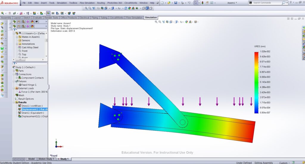
4.2 Interpreting Results: After simulation, engineers can analyze the results to gain insights into the structural behavior of the model. SolidWorks Simulation provides visualization tools for viewing stress contours, displacement plots, deformation animations, and other simulation outputs. Engineers can identify regions of high stress or deformation, assess the safety and reliability of the design, and make informed decisions about design modifications or optimizations.
Section 5: Optimization and Design Validation 5.1 Design Optimization: SolidWorks Simulation enables engineers to optimize designs for performance, weight, cost, or other objectives through iterative analysis and design optimization. Engineers can use optimization tools to automatically adjust design parameters such as dimensions, material properties, or load paths to achieve optimal design solutions while satisfying design constraints and requirements.
5.2 Design Validation: Once the stress analysis is complete, engineers must validate the design through testing and verification to ensure its safety and reliability. SolidWorks Simulation provides validation tools that allow engineers to compare simulation results with experimental data or analytical solutions. Engineers can perform sensitivity analysis and what-if scenarios to assess the impact of design parameters on performance and identify areas for improvement.
Conclusion: SolidWorks Simulation is a versatile and powerful tool for performing stress analysis and structural simulation of mechanical components and assemblies. By mastering the techniques outlined in this guide and leveraging the capabilities of SolidWorks Simulation, engineers can predict and analyze the behavior of designs with confidence, optimize designs for performance and reliability, and accelerate the product development process. With its intuitive interface, robust simulation capabilities, and seamless integration with SolidWorks CAD, SolidWorks Simulation empowers engineers to tackle complex engineering challenges and deliver innovative, high-quality designs.