Mastering Precision and Flexibility: An Extensive Guide to Parametric Modeling in SolidWorks
Parametric modeling lies at the heart of SolidWorks, serving as a cornerstone feature that empowers designers and engineers to create complex, accurate, and easily modifiable 3D models. This comprehensive guide delves into the depths of parametric modeling in SolidWorks, unraveling its functionality, benefits, and practical applications in various design and engineering scenarios.
Understanding Parametric Modeling:
Parametric modeling is a CAD (Computer-Aided Design) technique that enables the creation of 3D models based on mathematical parameters and relationships. In SolidWorks, parametric modeling allows users to define geometric shapes, dimensions, and relationships between features, providing a powerful framework for creating robust and flexible designs.
At the core of parametric modeling in SolidWorks lies the concept of parametric features, which are building blocks used to construct 3D models. These features include extrusions, revolves, sweeps, lofts, fillets, chamfers, holes, and more, each defined by specific parameters such as dimensions, angles, and relationships to other features.
Key Concepts of Parametric Modeling in SolidWorks:
- Feature-Based Modeling: Parametric modeling in SolidWorks revolves around the creation and manipulation of features. Features are individual geometric entities such as bosses, cuts, fillets, and holes that collectively define the shape and structure of the model.
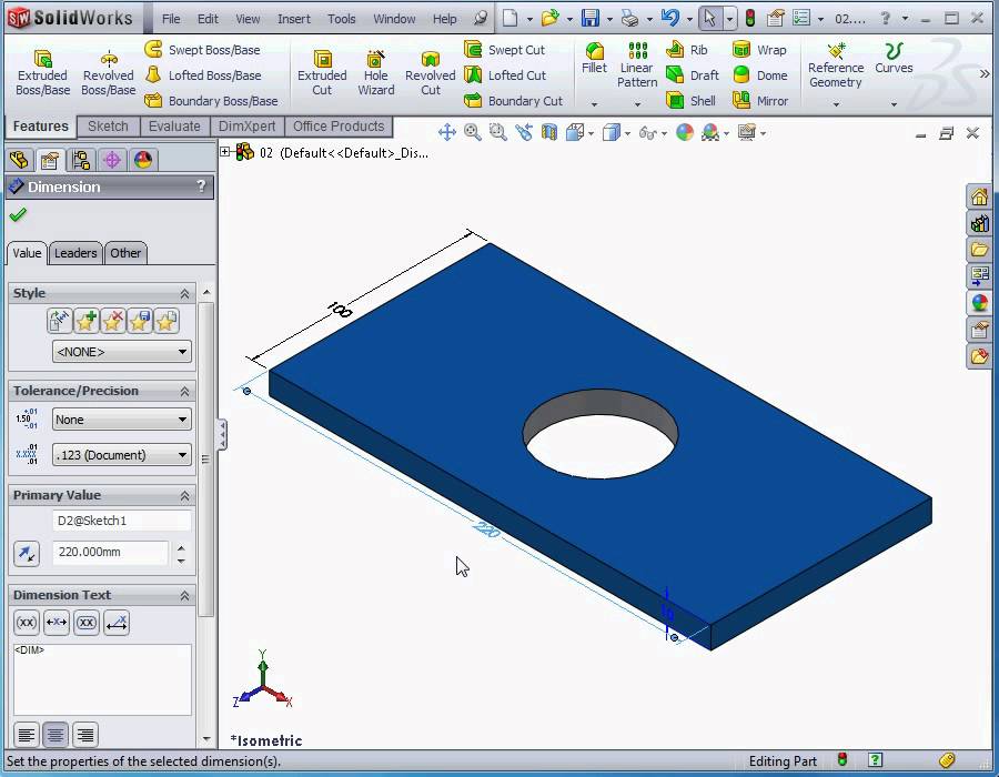
- Dimensional Control: Parametric modeling enables precise control over dimensions, allowing users to define and modify geometric properties such as length, width, height, radius, and angle. Dimensions can be specified numerically or driven by mathematical equations, providing flexibility and accuracy in design.
- Parametric Relationships: In SolidWorks, parametric relationships establish dependencies between features, ensuring that changes to one feature propagate to related features accordingly. These relationships include constraints such as coincident, concentric, parallel, perpendicular, and tangent, which help maintain geometric integrity and design intent.
- Design Intent: Parametric modeling in SolidWorks is driven by design intent, which refers to the underlying logic and constraints that govern the behavior and appearance of the model. Design intent ensures that the model behaves predictably and responds intelligently to modifications, preserving the designer’s original vision.
Benefits of Parametric Modeling in SolidWorks:
- Flexibility: Parametric modeling provides unparalleled flexibility, allowing designers to easily modify and adapt their models to meet changing requirements or design iterations. Parameters can be adjusted, dimensions can be edited, and features can be rearranged without sacrificing geometric integrity.
- Accuracy: Parametric modeling ensures high levels of accuracy and precision in 3D models, as dimensions and relationships are defined numerically and maintained dynamically. This accuracy extends to manufacturing and prototyping processes, where precise geometric data is essential for producing functional parts and assemblies.
- Efficiency: By capturing design intent and automating repetitive tasks, parametric modeling streamlines the design process and improves productivity. Design changes can be implemented rapidly, and design iterations can be explored iteratively, reducing time-to-market and enhancing competitiveness.
- Design Exploration: Parametric modeling encourages design exploration and innovation by enabling designers to experiment with different configurations, dimensions, and features. Through parametric relationships and constraints, designers can evaluate multiple design alternatives and optimize their solutions for performance, cost, and manufacturability.
Practical Applications of Parametric Modeling in SolidWorks:
- Product Design: Parametric modeling is widely used in product design across industries such as automotive, aerospace, consumer goods, and electronics. Designers leverage parametric modeling to create detailed 3D models of parts and assemblies, iterate on design concepts, and optimize product performance and aesthetics.
- Engineering Analysis: Parametric models serve as the basis for engineering analysis and simulation studies in SolidWorks. Engineers use parametric modeling to create finite element models, conduct stress analysis, thermal analysis, and fluid flow simulations, and evaluate the structural and functional performance of designs under various operating conditions.
- Manufacturing Preparation: Parametric modeling facilitates manufacturing preparation and documentation in SolidWorks. Designers generate 2D drawings, bill of materials (BOMs), and manufacturing instructions directly from parametric models, ensuring that accurate and comprehensive information is communicated to production teams.
- Collaboration and Communication: Parametric models serve as a common language for collaboration and communication among cross-functional teams in product development projects. Designers, engineers, manufacturers, and stakeholders can review, annotate, and analyze parametric models collaboratively, facilitating decision-making and consensus-building processes.
Conclusion:
Parametric modeling is a foundational technique in SolidWorks that underpins the creation of precise, flexible, and intelligent 3D models. By harnessing the power of parametric features, dimensional control, parametric relationships, and design intent, designers and engineers can unlock new levels of creativity, efficiency, and innovation in their design workflows. Whether used for product design, engineering analysis, manufacturing preparation, or collaboration, parametric modeling in SolidWorks remains an essential tool for realizing design concepts and bringing them to life with accuracy and precision.