Mastering Fluid Power System Modeling and Simulation in Automation Studio: A Comprehensive Guide

Introduction: Fluid power systems play a crucial role in various industrial applications, including manufacturing, construction, agriculture, and automotive sectors. Modeling and simulating fluid power systems are essential for designing, analyzing, and optimizing hydraulic and pneumatic components and circuits. Automation Studio is a leading software solution developed by Famic Technologies for modeling, simulating, and designing fluid power systems. In this comprehensive guide, we will delve into the intricacies of modeling and simulating fluid power systems in Automation Studio, covering everything from system design to simulation analysis and optimization techniques.
Section 1: Understanding Fluid Power Systems
1.1 Overview of Fluid Power Systems: Fluid power systems utilize pressurized fluids, such as hydraulic oil or compressed air, to transmit power and control motion in mechanical systems. These systems consist of various components, including pumps, actuators, valves, cylinders, and hoses, interconnected through fluid-filled circuits to perform work and achieve desired motion and force outputs.
1.2 Importance of Modeling and Simulation: Modeling and simulating fluid power systems are essential for predicting system behavior, evaluating performance, and optimizing design parameters. By creating accurate mathematical models and simulating system dynamics, engineers can analyze fluid flow, pressure distribution, energy consumption, and operational characteristics to ensure system reliability, efficiency, and safety.
1.3 Applications of Fluid Power Systems: Fluid power systems find applications in diverse industries and applications, including:
- Industrial automation: Hydraulic and pneumatic systems are used in factory automation, material handling, and process control applications for operating machinery, robots, and production lines.
- Mobile equipment: Fluid power systems power mobile machinery, such as construction equipment, agricultural machinery, and commercial vehicles, for lifting, pushing, pulling, and steering operations.
- Aerospace and automotive: Hydraulic systems are employed in aircraft flight control systems, landing gear, and braking systems, while pneumatic systems are used in automotive braking, suspension, and HVAC systems.
Section 2: Introduction to Automation Studio Software
2.1 Overview of Automation Studio: Automation Studio is a comprehensive software solution developed by Famic Technologies for modeling, simulating, and designing fluid power and automation systems. It offers a user-friendly graphical interface, extensive component libraries, and advanced simulation capabilities for engineers, designers, and educators.
2.2 Automation Studio Features and Capabilities: Automation Studio provides a wide range of features and capabilities for fluid power system design and simulation, including:
- Component libraries: Automation Studio offers extensive libraries of hydraulic and pneumatic components, including pumps, valves, cylinders, motors, and actuators, for building complex fluid power circuits.
- Circuit design tools: Automation Studio provides intuitive tools for creating, editing, and analyzing fluid power circuits, including schematic editors, symbol libraries, and circuit simulation capabilities.
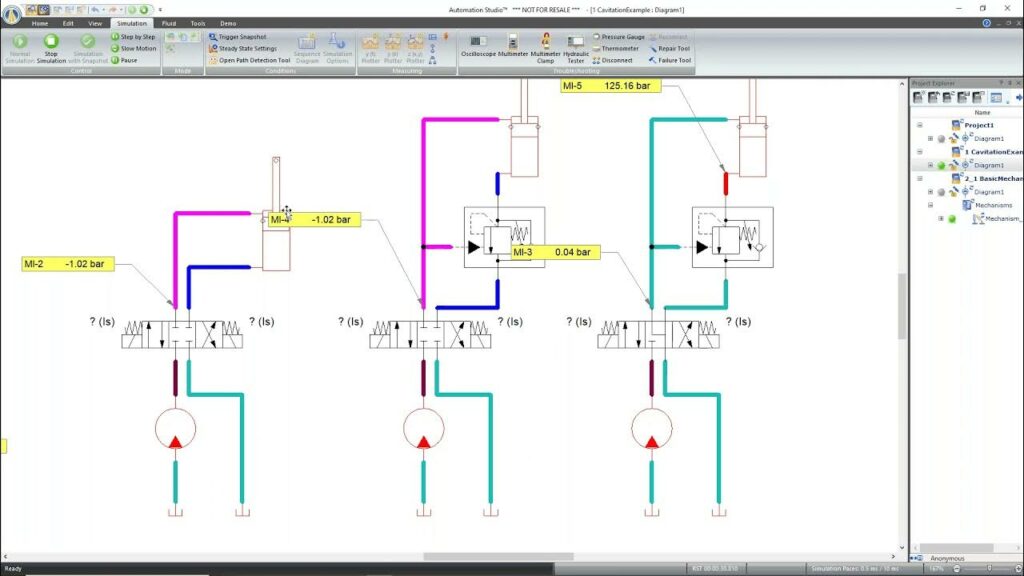
- Simulation environment: Automation Studio offers advanced simulation capabilities for modeling fluid flow, pressure dynamics, actuator motion, and control system behavior in real-time, enabling engineers to validate designs and optimize performance.
2.3 Benefits of Using Automation Studio: Automation Studio offers several benefits for engineers and designers involved in fluid power system design and simulation, including:
- Enhanced productivity: Automation Studio streamlines the design process with intuitive tools, customizable workflows, and automated simulation capabilities, reducing time-to-market and development costs.
- Accurate simulation: Automation Studio provides accurate and realistic simulation results, enabling engineers to predict system behavior, assess performance parameters, and identify potential issues before prototyping or production.
- Educational support: Automation Studio is widely used in educational institutions and training centers for teaching fluid power principles, system dynamics, and automation concepts through hands-on simulation and interactive learning experiences.
Section 3: Modeling Fluid Power Systems in Automation Studio
3.1 Component Selection and Placement: Engineers begin by selecting hydraulic and pneumatic components from Automation Studio’s extensive libraries and placing them on the workspace. Components include pumps, valves, cylinders, motors, filters, reservoirs, and pipes, which are interconnected to form fluid power circuits.
3.2 Circuit Design and Configuration: Using Automation Studio’s schematic editor, engineers design and configure fluid power circuits by connecting components with fluid lines, hoses, and connectors. They define circuit topology, specify component parameters, and set operating conditions to simulate system behavior accurately.
3.3 Fluid Properties and Parameters: Engineers specify fluid properties and parameters, such as viscosity, density, temperature, and pressure, to accurately model fluid behavior within the system. They define fluid properties based on the type of fluid used (e.g., hydraulic oil, water, air) and adjust parameters to match real-world conditions.
Section 4: Simulating Fluid Power Systems in Automation Studio
4.1 Dynamic Simulation: Automation Studio performs dynamic simulation of fluid power systems to predict system response, analyze performance, and validate design specifications. Engineers simulate fluid flow, pressure dynamics, actuator motion, and control system behavior to assess system behavior under different operating conditions.
4.2 Performance Analysis: Engineers analyze simulation results to evaluate system performance parameters, such as flow rates, pressure levels, actuator velocities, and energy consumption. They assess system efficiency, identify performance bottlenecks, and optimize design parameters to improve overall system performance.
4.3 Control System Integration: Automation Studio enables engineers to integrate control systems, sensors, and actuators into fluid power circuits for closed-loop control and feedback control applications. They design control algorithms, implement feedback loops, and simulate system response to validate control strategies and optimize controller parameters.
Section 5: Advanced Techniques and Optimization Strategies
5.1 Parameter Sensitivity Analysis: Engineers conduct sensitivity analysis to assess the impact of design parameters, component specifications, and operating conditions on system performance. They vary input parameters systematically, analyze simulation results, and identify critical factors influencing system behavior and performance.
5.2 Optimization Algorithms: Automation Studio offers optimization algorithms and tools for optimizing fluid power system designs and configurations. Engineers use optimization techniques such as genetic algorithms, particle swarm optimization, and gradient-based optimization to find optimal design solutions that meet performance objectives and constraints.
5.3 System Integration and Validation: Engineers integrate fluid power systems with mechanical, electrical, and control systems to simulate multi-domain interactions and validate system integration. They model interactions between hydraulic/pneumatic components and mechanical loads, electrical actuators, and control systems to assess overall system behavior and performance.
Section 6: Best Practices and Tips for Fluid Power System Modeling
6.1 Component Modeling: Accurately model hydraulic and pneumatic components by specifying detailed component parameters, such as flow coefficients, pressure ratings, response times, and efficiency curves. Use manufacturer datasheets, standards, and empirical data to ensure realistic component modeling and simulation.
6.2 Simulation Validation: Validate simulation results against experimental data, analytical models, or manufacturer specifications to ensure accuracy and reliability. Compare simulated results with measured data, conduct sensitivity analyses, and verify model assumptions to validate simulation accuracy and build confidence in results.
6.3 Collaborative Design: Foster collaboration and teamwork among engineers, designers, and stakeholders involved in fluid power system design and simulation. Use Automation Studio’s collaboration features, version control tools, and project management capabilities to streamline communication, share designs, and facilitate cross-functional collaboration.
Conclusion: Modeling and simulating fluid power systems in Automation Studio provide engineers and designers with a powerful toolset for designing, analyzing, and optimizing hydraulic and pneumatic circuits. By mastering the principles, techniques, and best practices discussed in this guide, engineers can leverage Automation Studio to create accurate models, simulate system dynamics, and optimize design performance for a wide range of industrial applications. With its intuitive interface, advanced simulation capabilities, and comprehensive libraries, Automation Studio continues to be a trusted platform for fluid power system modeling and simulation, empowering users to innovate and excel in the field of fluid power engineering and automation.


