Mastering the FILLET Command in AutoCAD: A Comprehensive Guide
AutoCAD, the industry-leading computer-aided design (CAD) software developed by Autodesk, provides a plethora of powerful tools and commands for creating precise and detailed drawings. Among these tools, the FILLET command stands out as a fundamental feature for rounding or chamfering the corners of objects within a drawing. In this comprehensive guide, we delve deep into the intricacies of using the FILLET command in AutoCAD, exploring various methods, techniques, and best practices for optimal utilization.
Understanding the FILLET Command in AutoCAD:
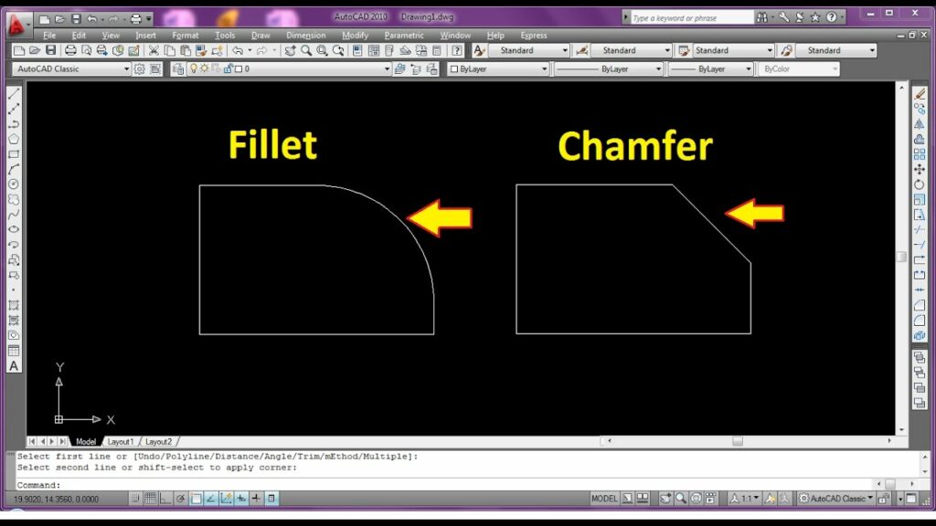
The FILLET command in AutoCAD allows users to create rounded or chamfered corners between two lines, arcs, or polylines, effectively smoothing transitions and enhancing visual aesthetics in drawings. It is a versatile tool for adding curvature or bevels to geometric entities, facilitating the creation of complex shapes and components. The FILLET command enables users to achieve precise rounding or chamfering of corners, enhancing drawing clarity and design appeal.
Using the FILLET Command:
AutoCAD offers multiple methods for using the FILLET command to modify objects in drawings:
1. Command Line Input:
The most straightforward method for using the FILLET command is through command line input. To apply fillets using the command line, follow these steps:
- Type “FILLET” in the command line and press Enter to activate the FILLET command.
- Specify the fillet radius or chamfer distance by entering a value or selecting a reference distance from existing geometry.
- Select the first object or line segment to fillet.
- Select the second object or line segment to fillet.
- Press Enter to complete the filleting operation.
2. Ribbon Interface:
AutoCAD’s Ribbon interface provides a graphical user interface for accessing commands and tools. To use the FILLET command from the Ribbon interface, follow these steps:
- Navigate to the Home tab on the Ribbon.
- Click on the Modify panel to expand it.
- Click on the Fillet icon to activate the FILLET command.
- Specify the fillet radius or chamfer distance using the options provided in the Ribbon interface.
- Select the first and second objects or line segments to fillet.
- Click OK or press Enter to complete the filleting operation.
3. Toolbar or Tool Palette:
Users can also access the FILLET command from toolbars or tool palettes for quick access and convenience. Simply click on the Fillet tool icon in the toolbar or tool palette to activate the FILLET command and follow the prompts to apply fillets.
Key FILLET Command Options:
When using the FILLET command in AutoCAD, users can specify various options and parameters to customize the filleting operation according to their requirements. Key options include:
- Fillet Radius: Specify the radius of the fillet curve, determining the curvature of the rounded corner.
- Chamfer Distance: Specify the distance of the chamfer, determining the length of the bevel at the corner.
- Multiple Fillets: Optionally, enable multiple fillets mode to apply fillets to multiple corner intersections simultaneously, streamlining the filleting operation for complex designs.
Advanced Techniques:
In addition to basic filleting methods, AutoCAD offers advanced techniques and tools for enhancing the FILLET command and efficiency:
- Variable Fillet Radius: Use the FILLET command with variable fillet radius option to apply varying radii to different fillet segments within the same operation, enabling greater control over fillet curvature.
- Fillet with Object Snaps: Utilize object snaps to accurately select endpoints or other key points for filleting, ensuring precise alignment and curvature of fillet curves.
- Fillet with Trim: Apply the FILLET command with trim option to automatically trim intersecting geometry to the fillet curve, providing clean and precise filleted corners.
Best Practices:
To achieve optimal results when using the FILLET command in AutoCAD, it’s essential to adhere to the following best practices:
- Plan and Preview: Before applying fillets, carefully review the drawing and plan the desired corner modifications, considering factors such as object relationships and design intent.
- Use Consistent Parameters: Maintain consistency in fillet parameters such as radius or chamfer distance to ensure uniformity and accuracy in the filleting operation.
- Optimize Object Selection: Select objects efficiently for filleting by using selection sets, filters, or object grouping, streamlining the filleting operation and minimizing errors.
- Review and Verify: Review filleted corners for accuracy and completeness before finalizing drawings, verifying curvature and alignment to ensure compliance with design specifications.
Conclusion:
In conclusion, mastering the FILLET command in AutoCAD empowers designers and drafters to modify corners with precision and efficiency. By understanding the various methods, options, and best practices for using the FILLET command, users can add curvature or bevels to corners with ease, enhancing drawing clarity and design aesthetics. With AutoCAD’s versatile tools and features, designers can achieve efficient filleting operations and enhance productivity in their drawings and designs.