Mastering Component Modeling: A Comprehensive Guide to Modeling Various Types of Fittings and Components in AutoCAD
James February 16, 2024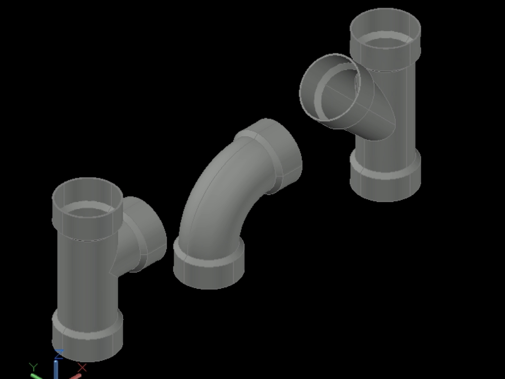
Introduction:
AutoCAD, a leading software in the field of Computer-Aided Design (CAD), empowers designers and engineers to create detailed and precise drawings of various systems. In this comprehensive guide, we delve into the intricacies of drawing piped systems from scratch in AutoCAD, exploring the tools, techniques, and best practices for creating accurate and well-documented representations of complex piping networks.
Section 1: Understanding Piped Systems in Engineering
1.1 Overview of Piped Systems: Begin with a foundational understanding of piped systems. Explore the diverse applications of piping in engineering, encompassing industries such as mechanical, civil, chemical, and process engineering. Understand the importance of accurate representations in design and documentation.
1.2 Types of Piped Systems: Delve into the different types of piped systems. Explore water supply and distribution systems, HVAC (Heating, Ventilation, and Air Conditioning) systems, industrial process piping, and more. Each type poses unique challenges and considerations in AutoCAD design.
Section 2: Setting Up the AutoCAD Environment for Piped Systems
2.1 Choosing the Right AutoCAD Template: Understand the importance of selecting the right AutoCAD template for piped systems. Learn how templates streamline the design process by providing predefined layers, linetypes, and settings tailored to piping drawings.
2.2 Configuring Units and Drawing Limits: Ensure precision in your drawings by configuring units and drawing limits. Explore the implications of unit settings on accuracy, and establish appropriate drawing limits to accommodate the scale and scope of your piped system.
Section 3: Basic Tools for Drawing Piped Systems
3.1 Lines and Polylines: Master the basics of drawing lines and polylines in AutoCAD. Learn how to use these fundamental tools to outline the path of pipes and define the layout of the system.
3.2 Circles and Arcs: Explore the use of circles and arcs in piped system drawings. Understand how to represent bends, curves, and circular components within the piping network.
Section 4: Essential Piping Components in AutoCAD
4.1 Inserting Standard Blocks: Familiarize yourself with standard blocks for piping components. Learn how to insert predefined blocks for valves, fittings, pumps, and other standard elements, streamlining the drawing process and ensuring consistency.
4.2 Creating Custom Blocks: Unlock the power of custom blocks in AutoCAD. Understand how to create personalized blocks for unique or specialized piping components, providing flexibility in representing diverse elements within the system.
Section 5: Utilizing Layers for Organization
5.1 Layer Organization: Master the art of layer organization in AutoCAD for piped systems. Explore how to use layers to categorize different components, maintain clarity in the drawing, and facilitate efficient editing.
5.2 Color and Linetype Assignments: Understand the significance of color and linetype assignments on layers. Learn how to use these attributes to distinguish between various piping elements, conveying information about the system at a glance.
Section 6: Creating Accurate Pipe Paths
6.1 Using the AutoCAD PLINE Command: Explore the use of the PLINE command to create accurate pipe paths. Understand how to draw continuous polylines to represent the routing of pipes, ensuring precision in the layout.
6.2 Specifying Pipe Sizes and Diameters: Delve into the specification of pipe sizes and diameters in AutoCAD. Learn how to incorporate accurate dimensions into your drawings, providing essential information about the scale and capacity of the piped system.
Section 7: Representing Fittings and Valves
7.1 Inserting Standard Fittings: Learn how to accurately represent fittings in piped systems. Understand the insertion of standard fittings such as elbows, tees, and reducers, aligning them seamlessly with the drawn pipe paths.
7.2 Customizing Fittings and Valves: Explore the customization of fittings and valves in AutoCAD. Understand how to adapt standard components to specific project requirements, ensuring a precise representation of the actual elements within the piped system.
Section 8: Creating Sections and Elevations
8.1 Generating Section Views: Delve into the creation of section views in AutoCAD for piped systems. Learn how to generate detailed sectional representations, providing insights into the internal layout and connections of the piping network.
8.2 Elevations and Isometric Views: Explore the generation of elevations and isometric views. Understand how to present a comprehensive and visually engaging representation of the piped system from different perspectives, aiding in design reviews and communication.
Section 9: Annotation and Documentation
9.1 Adding Dimensions and Annotations: Master the art of adding dimensions and annotations to piped system drawings. Explore how to convey critical information such as lengths, angles, and component labels, ensuring clarity and precision in your documentation.
9.2 Generating Bill of Materials (BOM): Delve into the generation of Bill of Materials (BOM) for piped systems. Learn how to extract information about the types, quantities, and specifications of components, facilitating material procurement and construction planning.
Section 10: Advanced Techniques for Complex Piped Systems
10.1 Utilizing the AutoCAD MEP Toolset: Explore the capabilities of the AutoCAD MEP toolset for piped systems. Learn how specialized tools within AutoCAD MEP enhance the efficiency of drawing complex piping networks, including features for routing, sizing, and analysis.
10.2 Clash Detection and Coordination: Understand the importance of clash detection and coordination in complex piped systems. Explore techniques for identifying and resolving clashes between piping components, ensuring the integrity and functionality of the system.
Section 11: Collaborative Workflows and Data Exchange
11.1 Collaborating with Other Disciplines: Explore collaborative workflows with other disciplines in AutoCAD. Understand how piped system drawings integrate with architectural, structural, and electrical disciplines, facilitating coordination and holistic project development.
11.2 Data Exchange with Other Software: Delve into data exchange between AutoCAD and other software platforms. Understand the importance of interoperability in collaborative projects and explore techniques for importing/exporting data to enhance workflow efficiency.
Section 12: Challenges and Troubleshooting
12.1 Common Challenges in Piped System Drawings: Address common challenges encountered in piped system drawings. From issues with connectivity to complexities in representation, gain insights into effective problem-solving strategies to ensure accurate and reliable drawings.
12.2 Troubleshooting Tips: Explore troubleshooting tips for resolving issues related to piped system drawings in AutoCAD. From optimizing performance to addressing conflicts with layers, understand how to maintain precision and stability in your design process.
Section 13: Future Trends and Emerging Technologies
13.1 Building Information Modeling (BIM) Integration: Delve into the integration of Building Information Modeling (BIM) with piped system drawings. Explore how BIM methodologies enhance collaboration, data exchange, and the overall efficiency of designing and documenting complex systems.
13.2 Augmented Reality (AR) for Piped System Visualization: Explore the potential of augmented reality (AR) for visualizing piped systems. Understand how AR technologies may provide designers and stakeholders with an immersive experience, allowing them to interact with and evaluate designs in real-world contexts.
Conclusion:
As we conclude this exhaustive exploration of drawing piped systems from scratch in AutoCAD, it is evident that mastering the art of piped system drawings requires a combination of technical skills, attention to detail, and an understanding of industry-specific requirements. Whether you are a mechanical engineer designing HVAC systems or a civil engineer planning water distribution networks, AutoCAD’s capabilities empower you to create accurate and comprehensive representations. Embrace the versatility, precision, and efficiency that AutoCAD offers in drawing piped systems, and witness how this transformative skill elevates your designs from concepts to detailed and well-documented plans. With continuous practice, exploration, and innovation, you will navigate the intricate landscape of piped system drawings with confidence, producing drawings that stand as testaments to the power of AutoCAD in the dynamic world of CAD.
Title: Mastering Component Modeling: A Comprehensive Guide to Modeling Various Types of Fittings and Components in AutoCAD
Introduction:
AutoCAD, a pioneer in Computer-Aided Design (CAD), provides designers and engineers with powerful tools to model a diverse range of fittings and components. In this comprehensive guide, we will explore the intricacies of modeling various types of fittings and components in AutoCAD, covering essential techniques, industry-specific applications, and best practices for creating detailed and accurate 3D models.
Section 1: Overview of Component Modeling in AutoCAD
1.1 The Importance of Component Modeling: Understand the significance of component modeling in the design and engineering process. Whether creating intricate mechanical parts or architectural elements, mastering the art of component modeling in AutoCAD is essential for accurate representation and visualization.
1.2 Types of Components: Delve into the diverse array of components modeled in AutoCAD. Explore mechanical fittings, architectural elements, electrical components, and more. Each type presents unique challenges and considerations in the modeling process.
Section 2: Setting Up the AutoCAD Environment
2.1 Choosing the Right Template: Start by selecting the appropriate AutoCAD template for component modeling. Learn how templates streamline the modeling process by providing predefined layers, linetypes, and settings tailored to various component types.
2.2 Configuring Units and Drawing Limits: Ensure precision in your component models by configuring units and drawing limits. Explore the implications of unit settings on accuracy and establish appropriate drawing limits based on the scale and complexity of the components.
Section 3: Fundamental Modeling Tools in AutoCAD
3.1 Lines and Polylines: Master the basics of drawing lines and polylines in AutoCAD. Learn how these fundamental tools serve as the building blocks for creating the outlines and profiles of various components.
3.2 Circles and Arcs: Explore the use of circles and arcs in component modeling. Understand how to incorporate curves, bends, and circular features, essential for representing a wide range of components accurately.
Section 4: Extrusion and Solid Modeling Techniques
4.1 Extrusion for 3D Components: Understand the concept of extrusion for creating 3D components. Learn how to convert 2D profiles into 3D objects using the extrusion command, providing depth and volume to your models.
4.2 Solid Modeling Features: Delve into advanced solid modeling features in AutoCAD. Explore commands like Union, Subtract, and Intersect to combine, cut, and create intricate shapes, enhancing the complexity and realism of your component models.
Section 5: Advanced Modeling Techniques
5.1 Revolve and Sweep: Unlock the power of revolve and sweep commands for advanced modeling. Understand how to create components with rotational symmetry or along a path, expanding the repertoire of shapes and features in your designs.
5.2 Loft and Blend: Explore loft and blend commands for creating complex transitions and surfaces. Learn how these advanced techniques enable the modeling of components with intricate shapes, such as ergonomic designs or fluid transitions.
Section 6: Customization and Parametric Modeling
6.1 Dynamic Blocks: Master the art of dynamic blocks in AutoCAD. Explore how to create blocks with adjustable parameters, allowing for flexible and dynamic component models that can adapt to different design scenarios.
6.2 Parametric Constraints: Delve into parametric constraints for precise and adaptable component modeling. Understand how to apply constraints to maintain relationships between different elements, ensuring that changes to one part of the model dynamically affect others.
Section 7: Model Components for Mechanical Applications
7.1 Gears and Mechanical Parts: Explore the modeling of gears and other mechanical components. Understand the precision required for accurately representing moving parts, and learn how to create parametric models to simulate various gear configurations.
7.2 Bolts, Nuts, and Fasteners: Master the modeling of bolts, nuts, and other fasteners in AutoCAD. Learn techniques for creating thread profiles, replicating standard fastener features, and ensuring accurate representations of these essential components.
Section 8: Model Components for Architectural Applications
8.1 Doors and Windows: Delve into the modeling of doors and windows in architectural components. Learn how to create parametric models that adapt to different sizes and styles, facilitating the efficient representation of architectural elements.
8.2 Stairs and Railings: Explore the modeling of stairs and railings. Understand how to use AutoCAD’s tools to create intricate stair designs and customize railings, ensuring accurate representation in architectural and structural drawings.
Section 9: Model Components for Electrical Applications
9.1 Circuit Components: Master the modeling of circuit components in AutoCAD. Learn how to create accurate representations of electrical components, such as resistors, capacitors, and connectors, for schematic diagrams and electrical drawings.
9.2 Custom Electrical Symbols: Explore the creation of custom electrical symbols. Understand how to model unique symbols for specific electrical components, ensuring clarity and consistency in electrical design documentation.
Section 10: Model Components for Plumbing and Piping
10.1 Pipes, Fittings, and Valves: Delve into the modeling of pipes, fittings, and valves for plumbing and piping systems. Learn how to create parametric models that represent the intricacies of plumbing components accurately.
10.2 Piping Networks: Explore the modeling of piping networks in AutoCAD. Understand how to design and model entire systems, considering factors such as flow direction, connections, and spatial relationships within the overall design.
Section 11: Annotation and Documentation
11.1 Adding Annotations and Dimensions: Master the art of adding annotations and dimensions to component models. Explore how to provide critical information such as measurements, materials, and specifications, ensuring clear and comprehensive documentation.
11.2 Generating Parts Lists and Bill of Materials (BOM): Delve into the generation of parts lists and Bill of Materials (BOM) for component models. Learn how to extract information about the types, quantities, and specifications of components, facilitating material procurement and construction planning.
Section 12: Collaborative Workflows and Data Exchange
12.1 Collaborating with Other Disciplines: Explore collaborative workflows with other disciplines in AutoCAD. Understand how component models integrate with mechanical, architectural, electrical, and plumbing disciplines, facilitating coordination and holistic project development.
12.2 Data Exchange with Other Software: Delve into data exchange between AutoCAD and other software platforms. Understand the importance of interoperability in collaborative projects and explore techniques for importing/exporting data to enhance workflow efficiency.
Section 13: Challenges and Troubleshooting
13.1 Common Challenges in Component Modeling: Address common challenges encountered in component modeling. From issues with complex shapes to parametric constraints, gain insights into effective problem-solving strategies to ensure accurate and reliable models.
13.2 Troubleshooting Tips: Explore troubleshooting tips for resolving issues related to component modeling in AutoCAD. From optimizing performance to addressing conflicts with constraints, understand how to maintain precision and stability in your design process.
Section 14: Future Trends and Emerging Technologies
14.1 Generative Design and AI in Component Modeling: Delve into the potential impact of generative design and artificial intelligence (AI) in component modeling. Explore how AI-driven tools may assist designers in generating innovative and optimized component designs, pushing the boundaries of creativity and efficiency.
14.2 Virtual and Augmented Reality (VR/AR) Integration: Explore the integration of virtual and augmented reality (VR/AR) with component modeling in AutoCAD. Learn how these technologies enhance the immersive experience of interacting with and evaluating component designs in real-world contexts.
Conclusion:
As we conclude this exhaustive exploration of modeling various types of fittings and components in AutoCAD, it is evident that mastering the art of component modeling requires a combination of technical skills, creativity, and an understanding of industry-specific requirements. Whether you are a mechanical engineer designing gears, an architect creating custom doors, or a plumber modeling piping systems, AutoCAD’s capabilities empower you to bring your ideas to life with precision and detail. Embrace the versatility, efficiency, and customization that AutoCAD offers in modeling various components, and witness how this transformative skill elevates your designs from concepts to tangible, detailed representations. With continuous practice, exploration, and innovation, you will navigate the intricate landscape of component modeling with confidence, producing models that stand as testaments to the power of AutoCAD in the dynamic world of CAD.