Mastering Angular Precision: A Comprehensive Guide to the DIMROTATED Command in AutoCAD
Introduction:
AutoCAD, a cornerstone in the world of computer-aided design (CAD), empowers architects, engineers, and designers with a diverse array of tools to create precise and detailed drawings. Among these tools, the DIMROTATED command stands out as a powerful feature for achieving angular precision in dimensioning. This extensive article delves into the intricacies of the DIMROTATED command in AutoCAD, exploring its functionalities, applications, and the transformative impact it has on achieving accuracy and clarity in dimensioning workflows.
Understanding the DIMROTATED Command in AutoCAD:
The DIMROTATED command in AutoCAD is designed to provide users with the capability to create rotated dimensions that accurately represent angular measurements within a drawing. This command allows designers to specify an angle of rotation for dimension lines, ensuring that dimensions align precisely with the geometry they intend to annotate. By offering angular precision, the DIMROTATED command enhances the readability and accuracy of dimensioning in AutoCAD.
Key Features and Functionalities:
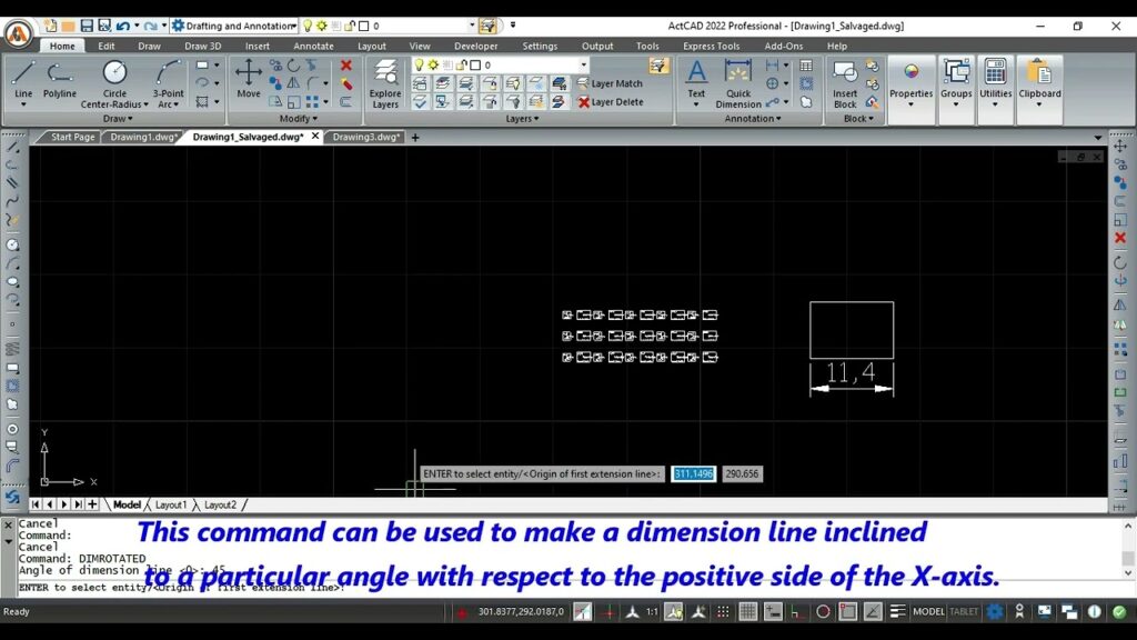
- Rotating Dimension Lines:
- The primary function of the DIMROTATED command is to rotate dimension lines at a specified angle.
- This rotation capability is particularly useful when dimensioning objects or features that are not aligned with the default horizontal or vertical orientation.
- Specifying Angle Values:
- Users can input precise angle values when utilizing the DIMROTATED command.
- This level of specificity allows for accurate alignment of dimension lines with inclined or rotated objects within the drawing.
- Angular Precision in Dimensioning:
- DIMROTATED enhances angular precision in dimensioning by providing a dedicated command for rotating dimension lines.
- This ensures that dimensions accurately reflect the angular relationships between various elements in the drawing.
- Dynamic Preview and Adjustment:
- AutoCAD provides a dynamic preview of the rotated dimension lines during the execution of the DIMROTATED command.
- Designers can adjust the angle interactively, observing the real-time impact on dimension lines before finalizing the placement.
Applications of the DIMROTATED Command:
- Dimensioning Oblique Objects:
- When dealing with oblique or non-orthogonal objects, the DIMROTATED command is essential for aligning dimension lines accurately.
- It allows designers to dimension features such as inclined walls, sloped surfaces, or rotated components with precision.
- Angular Dimensioning in Isometric Views:
- Isometric views often involve rotated or inclined elements that require angular dimensioning.
- DIMROTATED facilitates the creation of dimension lines that align with the angles of isometric projections, ensuring accurate representation.
- Dimensioning on Inclined Planes:
- In architectural or engineering drawings, elements on inclined planes may require dimensioning with respect to the inclination.
- DIMROTATED enables designers to align dimension lines precisely with the inclined features of the drawing.
- Detailing Mechanical Components:
- Mechanical drawings frequently involve components with non-standard orientations.
- The DIMROTATED command is instrumental in dimensioning intricate details of mechanical components, contributing to the clarity of manufacturing specifications.
Optimizing Workflow with the DIMROTATED Command:
- Accessing the DIMROTATED Command:
- The DIMROTATED command can be accessed through various methods, including the ribbon, toolbar, or by typing “DIMROTATED” in the command line.
- Familiarize yourself with the available options within the DIMROTATED command for customization.
- Specifying Angular Values:
- Input precise angular values when executing the DIMROTATED command to ensure accurate rotation of dimension lines.
- Understand the significance of positive and negative angle values based on the desired orientation.
- Utilizing Dynamic Input:
- Leverage dynamic input for real-time feedback when adjusting the angle during the execution of the DIMROTATED command.
- Dynamic input enhances the interactive dimensioning experience, allowing designers to make immediate adjustments.
- Incorporating into Dimension Styles:
- Dimension styles in AutoCAD offer the flexibility to customize the appearance of dimension text, lines, and arrows.
- Integrate the DIMROTATED command into dimension styles to create a cohesive and standardized approach to angular dimensioning.
Conclusion:
In conclusion, the DIMROTATED command in AutoCAD is a vital tool for designers seeking angular precision in their dimensioning workflows. Whether dimensioning oblique objects, isometric views, inclined planes, or detailing mechanical components, DIMROTATED enhances accuracy and clarity. As AutoCAD continues to evolve, the emphasis on features like the DIMROTATED command reflects the software’s commitment to providing users with tools that transcend traditional drafting boundaries. Embrace the power of DIMROTATED, and witness the transformation of your AutoCAD experience into a journey of angular precision, accuracy, and creative exploration within the vast landscape of CAD design.