Comprehensive Guide to Creating Section Views in SolidWorks Drawings

Introduction: SolidWorks, a leading computer-aided design (CAD) software, empowers engineers and designers to create detailed technical drawings that provide critical insights into design geometry, dimensions, and features. Section views are indispensable tools in SolidWorks drawings, allowing users to visualize internal structures, assemblies, and component relationships with precision. In this comprehensive guide, we’ll explore the intricacies of creating section views in SolidWorks drawings, covering fundamental concepts, essential techniques, and advanced strategies to help you master this vital aspect of CAD documentation.
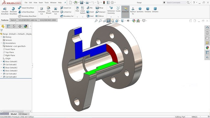
Understanding Section Views in SolidWorks: Section views in SolidWorks drawings are 2D representations of a 3D model sliced along a specified cutting plane or section line. These views reveal internal details, hidden features, and component relationships that may not be apparent from external views alone. Before delving into the specifics of creating section views, it’s crucial to grasp some foundational concepts:
- Cutting Plane:
- A cutting plane defines the plane along which the section view is created. SolidWorks provides tools for defining cutting planes, including cutting lines, sketch planes, and predefined section views (e.g., half-section, offset section).
- Section View Types:
- SolidWorks offers various types of section views, including full sections, half-sections, offset sections, aligned sections, and broken-out sections. Each type of section view serves a specific purpose in highlighting internal features, assemblies, or component interactions.
- Section View Properties:
- Section views in SolidWorks drawings can be customized with properties such as cutting line style, hatch patterns, hatch scales, and section view labels. These properties enhance clarity, readability, and visual differentiation of section views within the drawing.
Creating Section Views in SolidWorks Drawings: SolidWorks provides intuitive tools for creating section views, allowing users to visualize internal structures and component relationships accurately. Let’s explore the essential steps for creating section views:
- Activate Section View Tool:
- Begin by activating the Section View tool in the SolidWorks drawing environment. You can access the Section View tool from the View Layout tab or the right-click context menu. Select the desired section view type (e.g., full section, half-section) to begin creating the section view.
- Define Cutting Plane:
- Define the cutting plane by specifying the cutting line, sketch plane, or predefined section view orientation. SolidWorks provides options for selecting cutting planes parallel to standard planes (e.g., front, top, right) or custom planes defined within the model.
- Position and Orient Section View:
- Position and orient the section view relative to the drawing views to highlight the desired internal features, assemblies, or component interactions. Use alignment tools, such as alignment guides and snap points, to align the section view with existing views and drawing geometry.
- Adjust Section View Properties:
- Customize the properties of the section view, such as cutting line style, hatch pattern, hatch scale, and section view label. SolidWorks provides PropertyManager interfaces for editing section view properties efficiently and accurately.
- Update and Regenerate Drawing Views:
- After creating the section view, update and regenerate the drawing views to reflect changes in the section view geometry. SolidWorks automatically updates dependent views, dimensions, and annotations to maintain consistency and accuracy across the drawing.
Advanced Section View Techniques: In addition to basic section view tools, SolidWorks offers advanced techniques to enhance section view creation workflows and achieve precise documentation objectives:
- Multiple Section Views:
- Create multiple section views within the same drawing to highlight different internal features, assemblies, or component relationships. SolidWorks allows users to create multiple section views with independent cutting planes and properties.
- Offset Sections and Aligned Sections:
- Utilize offset sections and aligned sections to highlight specific regions or features within the model accurately. Offset sections create section views parallel to the original cutting plane at a specified distance, while aligned sections align section views with selected model edges or features.
- Broken-Out Sections:
- Create broken-out sections to focus on specific areas or components within the model while maintaining context with surrounding geometry. Broken-out sections remove material around a specified region, allowing for a closer inspection of internal details or complex features.
Best Practices for Section Views: To maximize clarity, accuracy, and effectiveness when creating section views in SolidWorks drawings, it’s essential to adhere to best practices:
- Define Cutting Planes Strategically:
- Define cutting planes strategically to highlight critical features, assemblies, or component relationships within the model. Consider factors such as part complexity, assembly structure, and design intent when selecting cutting planes for section views.
- Maintain Consistency and Clarity:
- Maintain consistency and clarity in section view properties, such as cutting line style, hatch pattern, and hatch scale, to ensure visual coherence and readability across the drawing. Use standardized section view settings to facilitate interpretation and understanding by stakeholders.
- Include Annotations and Callouts:
- Include annotations, callouts, and notes to provide additional context and information within section views. Use labels, arrows, and symbols to identify key features, dimensions, and components and clarify their significance in the design.
- Review and Validation:
- Review section views regularly to verify accuracy, completeness, and compliance with design requirements and documentation standards. Validate section views by cross-referencing with the 3D model, assembly drawings, and design specifications to ensure alignment and consistency.
Conclusion: Section views are indispensable tools in SolidWorks drawings, providing insights into internal structures, assemblies, and component relationships that may not be apparent from external views alone. By mastering the tools and techniques for creating section views, you can enhance your documentation proficiency, streamline your drawing workflow, and produce high-quality drawings that communicate design intent effectively. Whether you’re a novice or an experienced SolidWorks user, understanding the principles of section view creation and adhering to best practices will elevate your CAD skills and enable you to create clear, accurate, and informative technical documentation efficiently.


